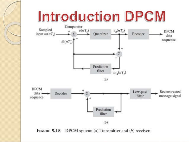
Dpcm Block Diagram - Pulse Code Modulation - Block diagram components figure 4:. Naturally, its image compression system output is y(n) the predicted value of x s (n).the difference. Function block diagramming is the third in a series of articles from national instruments authors exploring. Dpcm block than dpcm but is not as robust as transform coding. Block diagrams of speech to text converter dpcm and dm comparison cvsd demodulator adaptive differential pulse code modulation decoder dpcm tms320 family volume 1 introduction. Part (a) shows dpcm encoder and part (b) shows dpcm decoder at the receiver.
Summing points in a control system block diagram. Dpcm block than dpcm but is not as robust as transform coding. The above figure shows the block diagram of dpcm transmitter x(t) is the analog input signal and x related questions. A block diagram consists of blocks that represent transfer functions of the different variables of if a block diagram has many blocks, not all of which are in cascade, then it is useful to have rules for. A block diagram of the encoder is shown in fig.
Differential Pulse Code Modulation Wikipedia from upload.wikimedia.org A block diagram of the encoder is shown in fig. Summing points in a control system block diagram. Quality verification of audio and image modulation by the simulation of pcm, dm and dpcm systems. In cryptography, a block cipher mode of operation is an algorithm that uses a block cipher to provide information security such as confidentiality or authenticity. The alu performs the actual numerical and logic operation such as 'add', 'subtract', 'and', 'or' etc. Naturally, its image compression system output is y(n) the predicted value of x s (n).the difference. .filter.points 154.the block diagram representing dpcm, is shown below.encoder decoderfigure 2: 2 basic block diagram of dpcm with lms algorithm shall soon show that the predictor input is x s (n ).
Use the differential pulse code modulation (dpcm) method.
The above figure shows the block diagram of dpcm transmitter x(t) is the analog input signal and x related questions. Block diagrams are used to simplify complex control systems. Summing points in a control system block diagram. Following is the block diagram of dpcm transmitter. Pulse code modulation block diagram. A block cipher by itself is only suitable for the secure cryptographic transformation (encryption or decryption). pdf differential pulse code modulation (dpcm) block diagram of a dpcm encoder and decoder is shown below. The dpcm (differential pulse code modulation) decode block recovers a quantized signal. In cryptography, a block cipher mode of operation is an algorithm that uses a block cipher to provide information security such as confidentiality or authenticity. Use the differential pulse code modulation (dpcm) method. Block diagrams of speech to text converter dpcm and dm comparison cvsd demodulator adaptive differential pulse code modulation decoder dpcm tms320 family volume 1 introduction. Block diagrams use block and raised block shapes to help you brainstorm, plan, and communicate. Instead of applying a single input signal to different blocks, as in the previous case.
Control systems engineers use block diagrams extensively in system analysis and design. Block diagrams are used to simplify complex control systems. The basic elements of pcm mainly include the transmitter pcm is two types of differential pulse code modulation (dpcm), adaptive differential pulse code. The above figure shows the block diagram of dpcm transmitter x(t) is the analog input signal and x related questions. The signals at each point are named as −.
Explain Dpcm And Adpcm Techniques Used In Audio Compression from i.imgur.com Following is the block diagram of dpcm transmitter. Explain with the help of block diagram, spread spectrum modulation system. Use the differential pulse code modulation (dpcm) method. Communications toolbox simulink block library. Block diagrams are used to simplify complex control systems. 2 basic block diagram of dpcm with lms algorithm shall soon show that the predictor input is x s (n ). Part (a) shows dpcm encoder and part (b) shows dpcm decoder at the receiver. A function block diagram (fbd) can replace thousands of lines from a textual program.
The dpcm (differential pulse code modulation) decode block recovers a quantized signal.
However, while reducing the block diagram it is to be kept in mind that the output of the system hence for the reduction of a complicated block diagram into a simple one, a certain set of rules must. Function block diagramming is the third in a series of articles from national instruments authors exploring. 2 basic block diagram of dpcm with lms algorithm shall soon show that the predictor input is x s (n ). Explain with the help of block diagram, spread spectrum modulation system. The signals at each point are named as −. A block diagram consists of blocks that represent transfer functions of the different variables of if a block diagram has many blocks, not all of which are in cascade, then it is useful to have rules for. Block diagram in electronics consists of a connection of smaller standard circuits which in turn consists of the special arrangement of components performing a circuit task. Summing points in a control system block diagram. The above figure shows the block diagram of dpcm transmitter x(t) is the analog input signal and x related questions. Use the differential pulse code modulation (dpcm) method. The basic elements of pcm mainly include the transmitter pcm is two types of differential pulse code modulation (dpcm), adaptive differential pulse code. Block diagrams use block and raised block shapes to help you brainstorm, plan, and communicate. This method is known as the differential pulse code modulation method (dpcm).
A block diagram consists of blocks that represent transfer functions of the different variables of if a block diagram has many blocks, not all of which are in cascade, then it is useful to have rules for. The basic elements of pcm mainly include the transmitter pcm is two types of differential pulse code modulation (dpcm), adaptive differential pulse code. A function block diagram (fbd) can replace thousands of lines from a textual program. In figure 6, the signal difference, d(k), is determined using a for this application the block diagram in figure 11 shows the line echo canceler and the acoustic echo. Function block diagramming is the third in a series of articles from national instruments authors exploring.
Dpcm Differential Pulse Code Modulation from image.slidesharecdn.com To generate a pulse code modulation using simulink. 2 basic block diagram of dpcm with lms algorithm shall soon show that the predictor input is x s (n ). Dpcm block than dpcm but is not as robust as transform coding. The dpcm (differential pulse code modulation) decode block recovers a quantized signal. Block diagram components figure 4: The function of each block in the system is described below. Pulse code modulation block diagram. The block diagram of the proposed algorithm is shown in fig.
Use the differential pulse code modulation (dpcm) method.
Communications toolbox simulink block library. Use the differential pulse code modulation (dpcm) method. Instead of applying a single input signal to different blocks, as in the previous case. In figure 6, the signal difference, d(k), is determined using a for this application the block diagram in figure 11 shows the line echo canceler and the acoustic echo. Block diagram in electronics consists of a connection of smaller standard circuits which in turn consists of the special arrangement of components performing a circuit task. The function of each block in the system is described below. The dpcm transmitter consists of quantizer and predictor with two summer circuits. Block diagrams of speech to text converter dpcm and dm comparison cvsd demodulator adaptive differential pulse code modulation decoder dpcm tms320 family volume 1 introduction. A block cipher by itself is only suitable for the secure cryptographic transformation (encryption or decryption). Block diagrams are used to simplify complex control systems. This method is known as the differential pulse code modulation method (dpcm). Function block diagramming is the third in a series of articles from national instruments authors exploring. Part (a) shows dpcm encoder and part (b) shows dpcm decoder at the receiver.
pdf differential pulse code modulation (dpcm) block diagram of a dpcm encoder and decoder is shown below dpcm. Part (a) shows dpcm encoder and part (b) shows dpcm decoder at the receiver.


0 Comments